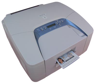
DILETTA 550i RFIDInkjet Passport Printer for E-PassportsHigh speed colour inkjet passport printing system with integrated contactless chip reader / writer for e-passports.
You can equip your DILETTA 500i passport printer with the optional integrated contactless chip reader / writer. So you can read and write in one pass the holder’s information during the print process. This avoids writing of wrong information into the passport which maybe can happen during a two step process caused by an operator mistake. The module supports all ISO 14443 type A and ISO 14443 type B chips with a transfer rate up to 848 kBit/s on Air Interface. DILETTA 550i Dual-RFID The DILETTA 550i Dual-RFID comes with two integrated RFID antennas inside of the passports sled. That ensures that the contactless chip of the e-passport can be read or written independent from the location of the RFID inlay. So the system can access to the chip in the front cover, back cover, data page or located somewhere in any inner page. The DILETTA 550i Dual-RFID is available with either auto-sensing or software-switching RFID module. The auto-sensing version sends the holders information automatically to the antenna located over the contactless chip. The version with software-switching RFID-module allows the individual selection of the RFID antenna by software command. Both systems ensure an easy and foolproof operation of the printers. Independent in which direction the operator inserts the passport the system can detect the correct location of the chip. Supported Tags
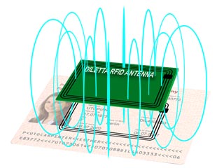
Global Interoperability 1) Contactless ICs operate at Radio Frequencies (RF). There are many different RF bands used, however the RF band defined in ISO/IEC 14443 and ISO/IEC 15693 is available worldwide. The use of ISO standards also avoids proprietary issues. Differences between ISO/IEC 14443 Type A and Type B contactless ICs 1) Type A contactless ICs are generally memory only ICs. The machine (RF) reader uses 100% amplitude modulation of the electromagnetic field for communication from the reader to the IC. That is, to communicate 1's and 0's the electromagnetic field is either on or off. During the time that the field is off, the IC must store enough energy in its internal capacitors to continue functioning. Type B contactless ICs are generally equipped with a processor IC. The processor consumes more power than a memory IC. Thus 100% amplitude modulation of the electromagnetic field for communication is not practical. Type B uses 10% amplitude modulation so the energy flow is not disrupted. Thus, to communicate 1's and 0's the electromagnetic field switches from 100% to 90% amplitude. Type A and Type B contactless ICs also have other operating differences, including different collision avoidance schemes. These differences are listed in the tables below Inductive Coupling 1) The machine (RF) reader provides an inductively coupled contactless IC with energy for its operation. To do this, the machine (RF) reader generates a strong radio frequency electromagnetic field in its antenna. The frequency used for ISO/IEC 14443 and ISO/IEC 15693 devices is 13.56MHz and the corresponding wavelength is 22.1m. This is several times the distance between the machine (RF) reader and the contactless IC (usually less than 1m). Thus in this close region the electromagnetic field can be regarded as a simple magnetic alternating field, as found in transformers. The strength of the electromagnetic field decreases quickly with the distance between the machine (RF) reader and the contactless IC. As the maximum strength of the electromagnetic field generated by the machine (RF) reader is set by regulations, taking into account safety considerations, reading distances of over 1m are not practical.
A part of the electromagnetic field generated by the machine (RF) reader covers the antenna of the contactless IC and induces an AC voltage across it. This AC voltage is converted into DC and is used to charge a capacitor. The charge on the capacitor is used to power the IC. Connected across the antenna is another capacitor. The value of this capacitance is chosen so that it works with the inductance of the contactless IC antenna to form a parallel resonant circuit. The resonant frequency of this circuit corresponds to the transmitted frequency of the electromagnetic field, and this gives the maximum voltage at the contactless IC. Data can be transmitted from the machine (RF) reader to the contactless IC by changing one parameter of the transmitted electromagnetic field ie amplitude, frequency or phase. 1) Reference ICAO 9303 For more information, e-mail us at info@diletta.com.
|